



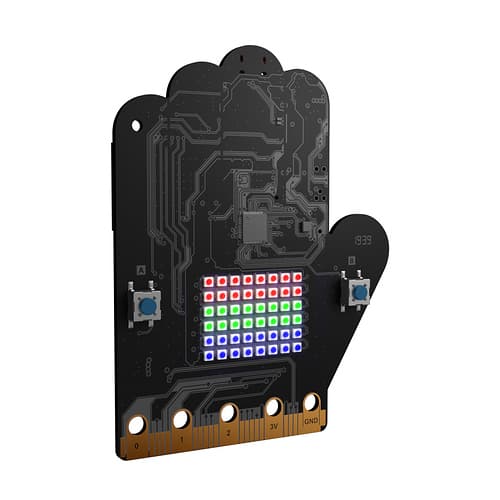




I had a Risc-V development board lying around, and I hadn't touched it in around 5 years, so I decided to try to get it to do something cool.
The board itself after some research is called the "SiFive Learn Inventor." It was a micro:bit compatible educational board that apparently was created in partnership with Tynker for teaching kids how to code. From the looks of it, it had a small LED matrix, a few buttons, accelerometer, an ambient light sensor, plus a Segger J-link debugger.
Initial Impressions
After doing more research, I learned that it was originally called the "BBC Doctor Who HiFive Inventor Kit," hence the hand-shaped board.
According to this "Technical User Guide" the board contains:
- SiFive RISC-V FE310-G003 SoC
- SEGGER J-Link OB Interface Chip
- 6 x 8 Neopixel LED Matrix (WS2812-2020)
- A reset button
- 2 x user buttons
- The LSM303AGR accelerometer/magnetometer
- The LTR-329ALS-01 ambient light sensor
- ESP32-SOLO-1 WiFi/Bluetooth module
Looking at some old Youtube videos, I found that the board could be programmed using block coding on Tynker's website, without the need for any additional steps. Learners could just plug in the board and start coding, and this worked using the SEGGER J-Link OB interface chip on the board and the WebUSB API in the browser.
This sounded like a really easy way to get started, so I plugged in the board to my computer, and searched for "Tynker BBC Doctor Who HiFive Inventor".
I found this blog post from Tynker: "The Doctor Who HiFive Inventor Coding Kit" and after reading through, I found a link hifiveinventor.com which was the place to sign in and start coding.
First Roadblock
I clicked on the link, and it took me directly to Tynker's main website, with no mention of the HiFive Inventor board. I tried searching for "HiFive" on the Tynker website, but got no results.
So, I had the idea to use Internet Archive's Wayback Machine to see if I could find an archived version of the hifiveinventor.com website. I entered the URL into the Wayback Machine and found that there were several snapshots of the website from 2018 and 2019
Unfortunately, because they were snapshots, I couldn't actually sign in or use the website to program the board. I could only see what the website looked like at that time. It didn't have much useufl info; mostly what was already said in the technical user guide, however, the website did mention that students could program the board using microPython as well.
microPython
Micropython is basically python for microcontrollers. It sounded promising since I had a lot of experience with Python and it would be a lot easier to use than C or C++. I searched for sources on how to get started with microPython on the HiFive Inventor board, but I barely found anything useful.
The first source was a blog post from CNX Software: "BBC Dr. Who HiFive Inventor Coding Kit Review". In the review the author mentions that micropython can be used through the Tynker website which has the micropython firmware for the board. However, since I couldn't access the Tynker website for the HiFive Inventor and I couldn't find any micropython implementations for the board anywhere else, this was a dead end.
The second source was another blog post by a Japanese Website called "DTS-Insight". The article talked about using micropython to code a simple compass on the LED matrix, but it did not go over how to install micropython on the board, or how to get started with it. It just assumed that the board comes with micropython pre-installed, which mine did not.
The arduino IDE
With micropython also being ruled out, I looked into using the Arduino IDE to program the board. SiFive has a Risc-V version of the Arduino Uno called the "HiFive1" which is very similar to the HiFive Inventor board. This board is actually well documented and has a lot of resources available online, including information on how to program it using the Arduino IDE.
With this in mind, I thought that maybe I could use the Arduino IDE to program the HiFive Inventor board as well. I followed online instructions to add the SiFive board manager URL to the Arduino IDE, and installed the SiFive board software.
However, when I tried to upload a simple "Blink" sketch, I got an error saying that a programmer was required to upload the code. I tried using the "Upload Using Programmer" option, but it still didn't work. I also tried using the Segger J-Link software to upload the code, but I couldn't get that to work either.
ESP32
The Segger J-Link software actually did connect to the board, and I got the SiFive logo printed in the terminal when I connected to the FE310-G003 chip. This meant that the J-Link was working, and I could use it to program the board.
However, it was clear that there was no arduino core for the board, so I couldn't use arduino sketches.
Interestingly, 2 USB devices showed up when I plugged in the board, which I realized was one for the ESP32 module and the other for the FE310-G003 chip. So I decided to give the arduino IDE another try, but this time I selected the ESP32 chip instead of the Risc-V chip. I installed the ESP32 board manager in the Arduino IDE, and selected the "ESP32 Dev Module" board. I was surprised when the code uploaded successfully, but as soon as it started executing, I got an error which I later realized was because the ESP32 on the board only had 1 core.
ESP32-SOLO-1
The ESP32-SOLO-1 is a single-core version of the popular ESP32 chip. It is designed for low-power applications and has a smaller footprint than the dual-core ESP32. However, this also means that the normal arduino cores for the ESP32 do not work with the SOLO-1, and a special core is required. I looked through github issues and other repositories but I could not find any cores for the ESP32-SOLO-1. So that meant I had to code it in C/C++ using the ESP-IDF framework developed by Espressif.
ESP-IDF
Searching up a simple I2C scanner script and then running it, I found no I2C devices connected to the ESP32. This meant that the accelerometer, magnetometer, and ambient light sensor were all connected to the RISC-V chip. The only other output remaining was the LED matrix, which I didn't know how to control, or where it was connected.
So, I decided on making the ESP32 a simple web server which would request data from the RISC-V chip over UART (serial) and then expose an API endpoint to get that data. This way I could easily access the sensor data for the web dashboard in TRACER.
Using the PlatformIO extension for VSCode, I set up the ESP-IDF framework and starting working on a simple web server.
The web server
I was initially thinking about connecting to my laptop via a websocket connection, as the laptop would be fetching data at a high frequency. However, the esp-32 doesn't support SocketIO (makes it much easier to communicate via websockets), and instead only supports basic websockets, so I continued on with the web server. ESP-IDF has a library called esp_http_server which makes it easy to create a web server:
To make this useful, I registered a new /sensor API endpoint / server route which would return the latest sensor data from the RISC-V chip. But before I could do any of this, I had to figure out several things:
- What kind of data and components were available on the RISC-V chip?
- How to communicate with the RISC-V chip over UART/Serial?
- How to run simulataneous tasks on the ESP32?
Sensor Data on the RISC-V Chip
After seeing the Technical User Guide, I already knew what sensors were available on the RISC-V chip, but to actually understand what data each sensor sent, I had to look at the datasheets for each one.
The LSM303AGR
From the datasheet the LSM303AGR is described as an:
Ultracompact high-performance eCompass module: ultralow-power 3-axis accelerometer and 3-axis magnetometer
The 3-axis accelerometer measures acceleration in all 3 axes, which can help determine orientation while stable by using gravitational acceleration as a reference. On the other hand, the 3-axis magnetometer serves as a digital compass, measuring the magnetic field strength along each axis.
Additionally, the sensor contains an I2C serial bus for fast communication.