



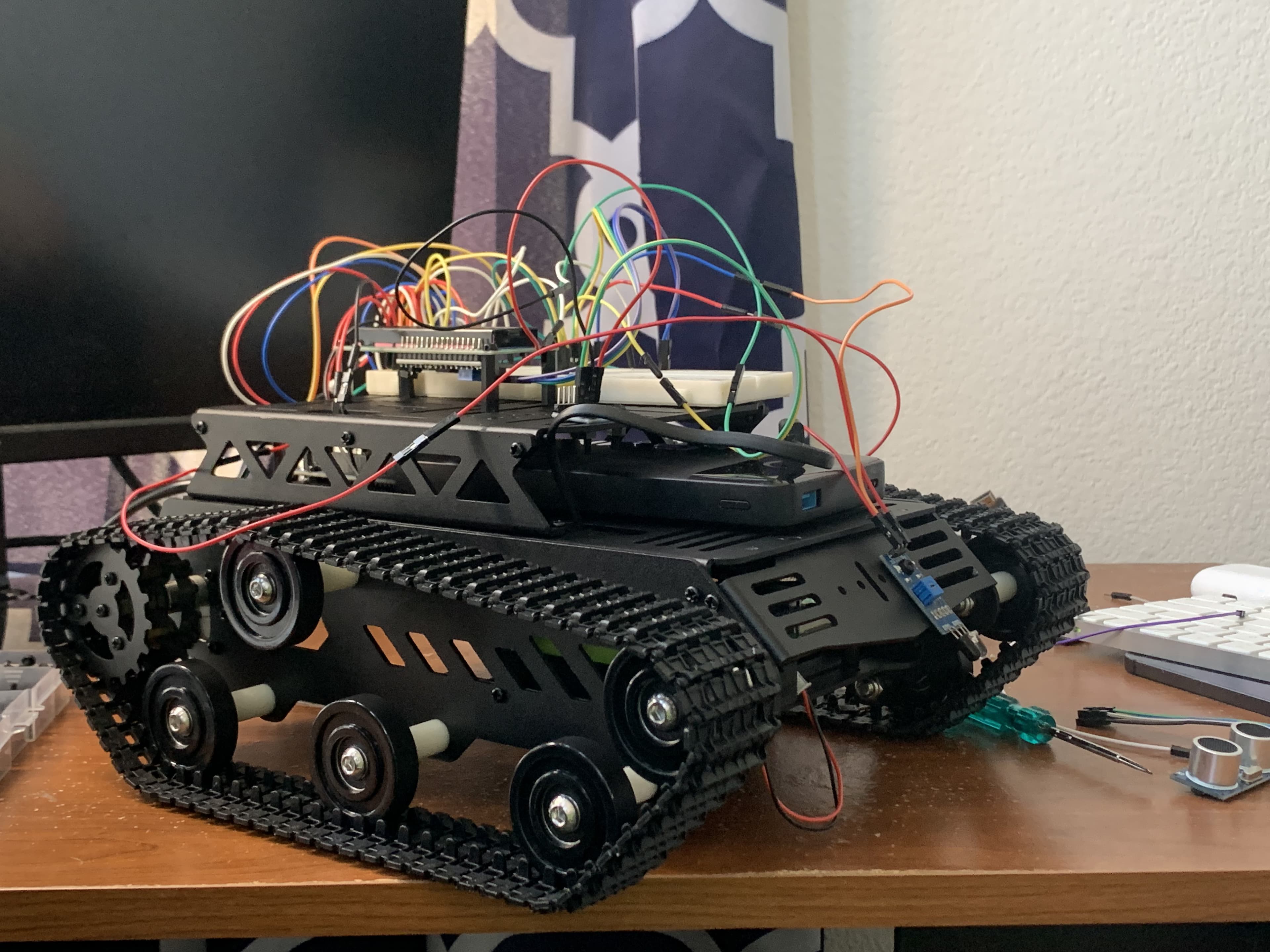











I started working on TRACER about a month after GPTKitbot, in which I tried to make ChatGPT control an FRC Robot. Unfortunately, I didn't have enough time before robotics ended to fix the final few bugs I had, but the project was still a great learning experience. So, ever since then I was planning to make an even better, more sophisticated AI-controlled robot car or tank fully from scratch. No high-level FRC WPILib; I instead wanted to start with arduino and build up from there.
Goals
I wanted TRACER to meet the following goals:
- Be able to type a prompt or query and have the robot execute it. (e.g. Drive forward for a bit then turn left and drive backwards)
- View sensor data and control the robot from a dashboard
- Drive it with my xbox controller and use the rumble feature for haptic feedback
- Detect and avoid obstacles.
Parts List
After a few weeks of planning and then getting following parts, I started working on TRACER.
- Arduino Uno R3
- MPU-6050
- HC-SR04 Ultrasonic Sensor
- HC-05 Bluetooth Module
- TB6612FNG Motor Driver
- 3-pin IR Sensor
- 2x 18650 Li-ion Batteries
- Raspberry Pi 3B+
- Tank Chassis
- 16x2 LCD Display
- Screws and spacers
- And resistors, wires, and a breadboard.
Hardware
I first started with the hardware which was a bit of a challenge since the last time I did anything with embedded was in 7th grade for a science fair project. Assembling the chassis was easy, but then I had to wire the motors, sensors, and arduino. After a bit of trial and error, I finally figured out how to wire the TB6612FNG motor driver.
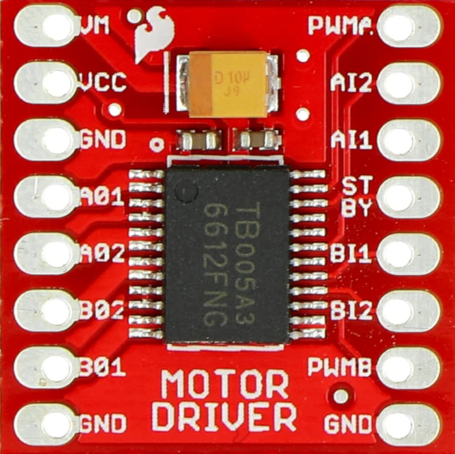
The motor driver was fairly simple, it can control 2 motors and has one PWM pin for each motor, PWM A and PWM B, and two direction pins for each, AIN1, AIN2, and BIN1, BIN2.
The PWM pins control the speed of the motors and can take values from 0 to 255. In arduino this is just done with the analogWrite function which generates a PWM signal on the defined pin.
Only certain pins on the arduino support PWM. Make sure to connect PWMA and
PWMB to the PWM capable pins
In essence, PWM works by making a specific signal that turns the pin HIGH for a certain amount of time, and then LOW for the rest of the time. The ratio of HIGH to LOW time is called the duty cycle, and it determines the average voltage output of the pin. For example, if the duty cycle is 50%, the pin will be HIGH for half the time and LOW for the other half, which results in an average voltage of 2.5V on a 5V pin. This is useful since it allows us to control the speed of the motors by changing the duty cycle of the PWM signal.
The direction pins control the direction of the motors, and can be set to either HIGH or LOW. If both direction pins are set to LOW, the motor will stop. If one direction pin is set to HIGH and the other is set to LOW, the motor will spin in one direction, and if the other direction pin is set to HIGH and the first one is set to LOW, the motor will spin in the other direction.
These directions depend on how the motors are wired, so you may need to reverse the direction of one of the motors in your code while testing.
The motor driver also has a STBY pin which must be high or connected to 5V for the motors to be enabled.
The VCC pin is connected to 5V, and the GND pin is connected to ground.
The final power pin is the VM pin which is connected to the battery.
Do not connect the VM pin to the arduino 5V pin, as this will damage the
arduino. Make sure to connect it to the battery instead. With 2 18650
batteries at 3.7V each, the total voltage is 7.4V which is within the range of
the motor driver.
Finally, there are 4 output pins for each motor, A01, A02, B01, and B02, which are connected to the motors. You can also change the direction the motors spin by swapping the wires to A01 and A02 or B01 and B02.
The code for controlling the motors is really simple:
In this code, we drive the motors using 2 values: leftSpeed and rightSpeed, which are both between -255 and 255.
Make sure to enable output on the pins used here in your code, otherwise the motors will not work.
This may look confusing at first: How do we turn without a way to change the angle of the wheels like in a car? Well, this robot uses a method of steering known as differential drive. Using differential drive, we can control the speed of each motor independently to turn the robot. For example, if we want to turn left, we can set the left motor to a negative speed and the right motor to a positive speed. This will cause the robot to spin left. Alternatively, just setting the left speed to 0 makes the robot turn left while moving forward.
In the code we then determine the direction pin values based on the signs of the speeds. Finally, we use analogWrite to set the PWM value for each motor, making sure to flip the sign of the speed if its negative.
I also connected the standby pin to a digital pin for an emergency stop feature.
Sensors
I wanted TRACER to have some sort of obstacle avoidance, even if it was very basic. So, I decided to use an ultrasonic sensor to measure distance to obstacles in front of the robot. I also used 2 IR sensors pointing down on the back and front of the robot to detect if the robot is about to fall off a ledge or something similar.
Ultrasonic Sensor
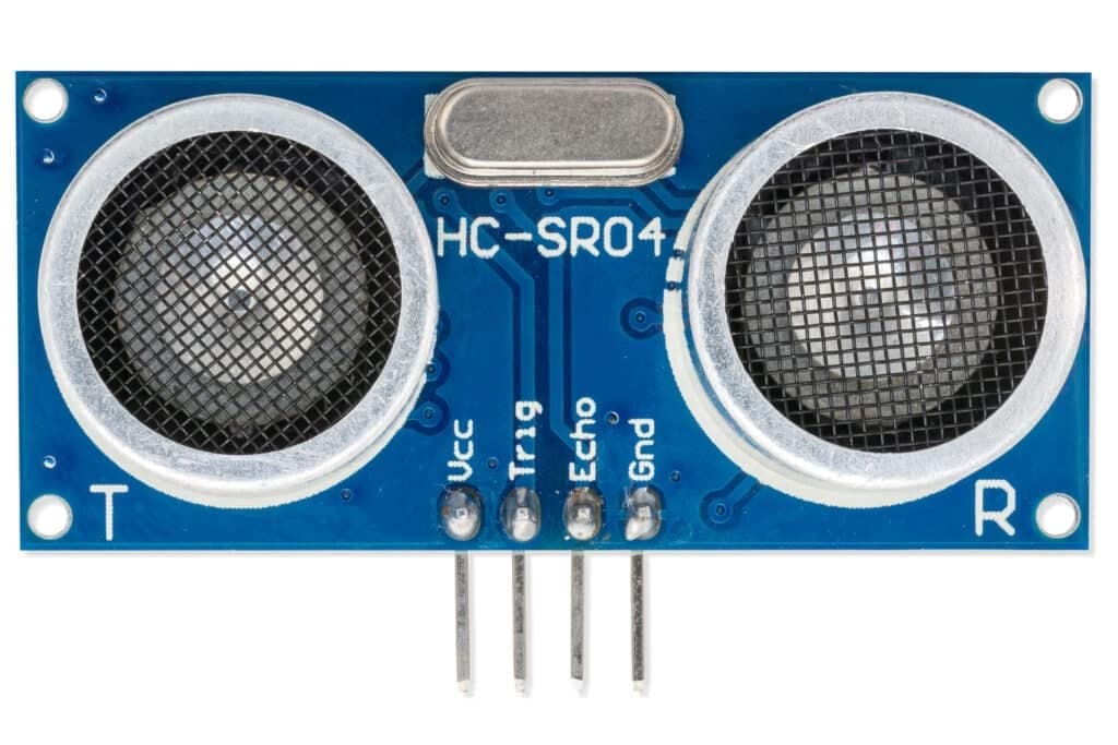
The ultrasonic sensor has 4 pins, VCC, GND, TRIG, and ECHO.
The VCC pin is connected to 5V, the GND pin is connected to ground, the TRIG pin is used to send out the sound wave, and the ECHO pin is used to receive the sound wave.
When the TRIG pin is set to HIGH, the ultrasonic sensor will send out a sound wave and from this we can use the ECHO pin to measure how long it takes for the sound wave to return.
This works by sending out a very high frequency sound wave and then measuring how long it takes to return. Sound waves will bounce of close enough objects, and from the total time it takes from sending to receiving the sound wave, we can calculate the distance to any objects.
Sound travels at about 343 meters per second, so to calculate distance we can use the formula:
Where d is the distance in meters, and t is the time in seconds. The division by 2 is because the sound wave has to travel to the object and back, so the total time is double the distance.
The ultrasonic sensor will send out a pulse when the sound wave is sent out, and then another pulse when the sound wave is received on the ECHO pin. In arduino we can use the pulseIn function to measure this interval.
This works well in most cases, but there are 2 major edge cases that lead to issues:
- If the object is too close, the sound wave will return while the original pulse is still being sent out, and this messes up the readings.
- If the object is too far away, the sound wave will not return in time and there won't be any reading.
This caused issues with the obstacle detection, so I had to add some extra logic to handle this.
I set a timeout of 25ms for the pulseIn function, which is about 4.25 meters. If the duration is 0, it means the object is too far away, and we return -1. If the duration is less than 100 microseconds, it means the object is too close, and we return -2.
This is useful for processing the distance later on, as we can keep a history of the last 10 distances. If we get an invalid reading we can use the average of the previous readings to estimate a value, and then add that to the history. This is basically implementing a simple smoothing mechanism to mitigate discontinuities.
The code above is taken from the raspberry pi side which I will explain in depth later on.
IR Sensors
I had a few simple 3-pin IR sensors lying around, so I decided to use them to detect if the robot is about to fall off a cliff or ledge. The IR sensor works by emitting IR light and then measuring the amount of light that's reflected back. So the idea is to point the IR sensor straight down, if we are close to the ground we should get some light reflected back, and if we are far above the ground we should get barely any or no light reflected back.
This isn't the best since the IR sensor has to be tuned based on the surface using the potentiometer on it. It also will change its readings in different lighting conditions, so it works for a rough estimation of a cliff, but not for precise measurements.
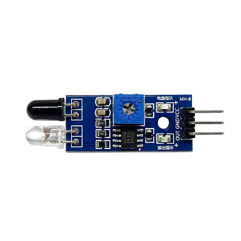
The IR sensor has 3 pins, VCC, GND, and OUT. The VCC pin is connected to 5V, the GND pin is connected to ground, and the OUT pin is connected to any arduino pin, and can be read with digitalRead.
The potentiometer is just the small blue knob, and I found that it was easiest to turn with a screwdriver.
The code is very simple, just reading the OUT pin and checking if it's HIGH or LOW. If it's HIGH, it means the sensor is detecting the ground (no cliff), and if it's LOW, it means the sensor is not detecting any ground (cliff)
Again, later on this is used for automatic stopping and haptic feedback if we encounter a cliff on any side.
MPU-6050
The MPU-6050 is a 6-axis motion tracking device that combines a 3-axis gyroscope and a 3-axis accelerometer. Since it is an I2C device, the code is a bit more complicated than the other sensors. At first, it seemed kind of confusing, but the Arduino Wire.h library makes reading I2C much easier than coding with bare metal (which I had to do later on for another board).
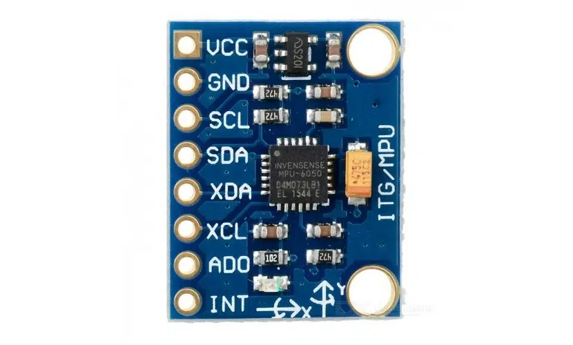
The MPU-6050 also has a DMP (Digital Motion Processor) which does sensor fusion onboard to get orientation, but I didn't end up use it, or the accelerometer yet. I just have this in case I use it later for estimating relative position and pose for path following algorithms.
The sensor has 4 pins, VCC, GND, SDA, and SCL. The VCC pin is connected to 5V, the GND pin is connected to ground, the SDA pin is connected to the arduino's I2C data pin, and the SCL pin is connected to the arduino's I2C clock pin. The SDA and SCL pins are what allow I2C communication.
After a lot of research I realized that I2C communication is just specially timed pulses on the SDA pin which is synchronized by the clock pin. It's like morse code, but with a clock signal to synchronize the data. When the clock is high, the data on the SDA pin is supposed to be valid, which means it's suitable for reading. In this way, binary data can be transmitted over the I2C bus.
The MPU-6050 has a default I2C address of 0x68; if this doesn't work you can
run a scanning script to scan the I2C bus and find the address of the
sensor.
Make sure to connect the SDA pin to the designated I2C data pin on the
arduino, and the SCL pin to the designated I2C clock pin. On the Arduino
Uno, these are pins A4 and A5 respectively. If this is done incorrectly,
the sensor will not be able to communicate with the arduino.
The MPU exposes a lot of different data, like temperature, acceleration in xyz, and angular velocity in xyz. The way this is read is using registers. Basically, we can read a register by first sending the register address to the sensor, then the sensor will send the data from that register back to us. There are more registers for configuring the sensor with interrupts and other modes like FIFO or low power mode, but for this use I only needed to read from the data registers, and just write to the power mode register to turn the sensor on.
Each data register has 1 byte of data, however the actual data for each value is 16 bits (2 bytes), so there are 2 registers for each value. One register stores the "low" byte and the other register store the "high" byte. Now the sensor could send the high byte first, or low byte first, but we can specify this to make sure we read the data correctly. This is known as the endianness of the data, and in this case the default is big-endian, which means the high byte is sent first and then the low byte.
To combine both bytes into a single value we basically need to concatenate them. Just like how we can concatenate strings high + low (if they were strings), we can concatenate bytes by shifting the high byte 8 bits to the left and then adding the low byte.
The following code reads the MPU-6050 data registers.
For this code to work we first need to initialize wire transmission and power on the MPU.
LCD Display
I also had a small 16x2 LCD, so I decided to use it to show some current state (e.g. "Ready", "Moving", "Stopped", etc.). Also, this could be used to allow the robot to "say" things like "Hello World!" or "I am TRACER!".
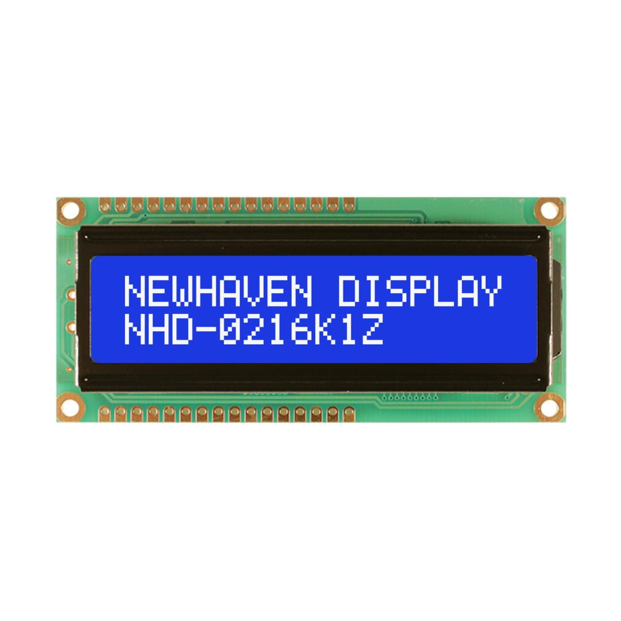
The LCD has a lot of pins, but with an I2C backpack, we can make the LCD an I2C device and just use the 4 pins from earlier. Luckily there are already libraries for this, so the code isn't as complicated as the MPU-6050.
I used the LiquidCrystal_I2C library to control the LCD. The library makes it really easy to print text to the display, and it also handles the I2C communication for us.
The LCD display has a default I2C address of 0x27, but this can vary
depending on the backpack used. If this doesn't work, you can run a scanning
script to scan the I2C bus and find the address of the display.
To set up the display we need to initialize an lcd instance with the address and the number of columns and rows. Then we can use the init method to initialize the display.
Battery Percentage Estimation
Later on in the project I noticed a slight issue with the lithium batteries. Overnight, the batteries would slowly discharge and this would lead to slower movement and less power. So I wanted to estimate the battery percentage by measuring the voltage and comparing it to the maximum voltage of the batteries. Since I used 2 batteries in series, the maximum voltage is 8.4V (2 _ 4.2V), and the minimum voltage is 6.0V (2 _ 3.0V).
To measure the voltage, I used a voltage divider to step down the voltage to a range that the arduino can read. The arduino's analog pins can only read voltages between 0 and 5V, so we need to step down the voltage from 8.4V to 5V. I used a 10k and 3k resistor to create a voltage divider, which gives us a ratio of 3 / 13. This means that the maximum voltage we can read is 5V _ (3 / 13) = 1.15V, and the minimum voltage is 0V _ (3 / 13) = 0V. (More info on voltage dividers below in the bluetooth section) I also connected the battery after the voltage divider to an analog pin on the arduino.
The code to read the battery voltage and get percentage just uses analogRead.
The next step: Connecting the hardware side to a proper computer
My initial architecture was to have the arduino act as a slave device. It would just read sensors and send sensor data to the computer, and then the computer would send commands to the arduino to control the motors or LCD.
So, I first looked into using bluetooth. My plan was to connect the bluetooth module to the arduino and then connect to it from my laptop via python. Then my laptop could function as the "brain" of the robot, processing the sensor data and sending commands to the arduino. I bought the HC-05 bluetooth module, which is a very common bluetooth module for arduino projects. It can be used to send and receive data over bluetooth, and it has a simple serial interface. However, what I didn't realize was that the HC-05 did not support Bluetooth Low Energy (BLE). The HC-05 is pretty old, and as a result it doesn't work with ios devices which explicitly require BLE for bluetooth communication. After doing some research I got mixed answers on whether the HC-05 would work with a Mac or not. So I just decided to try it out and see if it works.
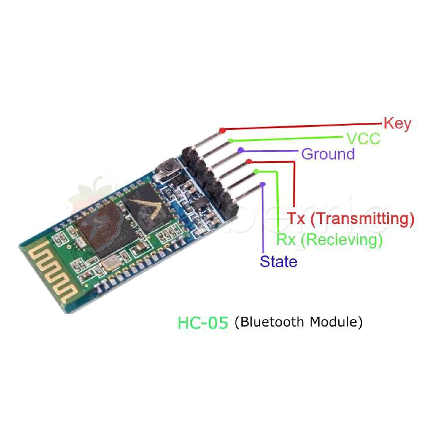
The golden zigzag line is the antenna. The power pins are of course VCC and GND, and the other pins are TX (transmit) and RX (receive) which are used for serial communication. The EN pin is used to enable the module, but I didn't end up using it since I just connected it to power.
Since I wanted to keep the hardware serial open for debugging, I used the SoftwareSerial library to create a new serial port for the HC-05. This way I could still use the hardware serial for debugging and the software serial for bluetooth communication. I connected the TX and RX pins to digital pins 10 and 11 respectively, and then used the SoftwareSerial library to create a new serial port.
The GPIO pin connected to the TX pin of the HC-05 should be set to INPUT,
and the GPIO pin connected to the RX pin of the HC-05 should be set to
OUTPUT. This is because the HC-05 will send data on the TX pin and receive
data on the RX pin. It's just like connecting hardware serial on other
devices. YOu won't connect TX to TX or RX to RX, but instead TX to RX and RX
to TX.
Just like I2C, serial communication is also a way to send data over a single wire. The HC-05 uses a serial interface to communicate with the arduino, which is just a way to send and receive data over a single wire. We specify a baud_rate which is the speed at which bits are sent (bits/second). The default is 9600 baud which is recommended for Software
Serial; however, higher baud rates can be used with the built-in hardware serial pins (0 and 1) on the arduino.
Initially I just connected the HC-05 VCC to 5V, and this worked, but there was a subtle issue. The HC-05 is rated for 5V, but the RX pin is only rated for 3.3 V. So I had to use a voltage divider.
The formula for a voltage divider is:
Where Vin is the input voltage, Vout is the output voltage, and R1 and R2 are the resistors in the voltage divider.
Since we want to step 5V down to 3.3 V, we need the ratio (R2 / (R1 + R2)) to be 3.3 / 5 = 0.66 = 2/3. So the ideal resistors should be R1 = 1 kOhm and R2 = 2 kOhm. However, I only had 1 kOhm and 10 kOhm resistors, so I replaced R2 with 2 1k0hm resistors in series, which gives the same ratio.
With the voltage divider, I thought the bluetooth module would work, and I started writing arduino code to send sensor data.
Initially I planned to send sensor data as a JSON string using the ArduinoJson library, but I realized that this was very inefficient. Bluetooth communication is similar to serial communication. So using a json string would require sending a lot of unnecessary data and this would increase latency, especially over bluetooth.
Instead, I opted for a compact binary packet format.
In this packet, there are a total of 24 bytes, which is way more efficient and compact than a JSON string. (Floats take up 4 bytes, and int16_t takes up 2 bytes)
The start byte is used to indicate the start of a new packet, and the checksum is used to verify the integrity of the packet. The checksum is just the sum of all the bytes in the packet, modulo 256. This way we can detect if any bytes were corrupted during transmission.
The checksum is done modulo 256 so as to fit in a single byte. This is also
equivalent to doing sum & 0xFF (bitwise AND with 255).
The IR flags are a bit different from the other data, since they are both booleans. I just set the first bit to the value from the front IR sensor, and the second bit to the value from the back IR sensor. This way we can pack both values into a single byte and then use bitmasks or bitwise operations to extract the values later on.
The arduino code to create this packet is as follows:
In this code I also just read from cached data for distance, accelerometer, gyroscope, and battery data. This is to minimize the time it takes for a sensor packet to be created and sent. I noticed that when I read all values from the sensors while making the packet, data took around 50 ms to get back, while caching them and just sending the cached values took around 2-3 ms. The way they are cached is fairly simple, I just read the sensors at intervals and store their data in a global variable.
The battery data is also cached, but in a slightly different way. The battery voltage drops sharply when the motors are running, so I only read the battery voltage when the motors are not running.
Then from the python side, I could just use pyserial to read 24 bytes of data at a time when they were available. If the checksum didn't match our calculated checksum we would just discard the packet and wait for the next one.
Using python's struct module, we can easily unpack the binary data into the corresponding types.
The Bluetooth Module
This unpacking and processing was only figured out after a fundamental shift in the project because of one big issue: the HC-05 bluetooth module.
No matter what I tried, I could not get data to be sent over bluetooth. The bluetooth module paired to my laptop but no data was being sent. I tried using the AT commands to configure the module, but it just didn't work. I tried using different baud rates, different configurations, and even different libraries, but nothing worked. I even tried connected the HC-05 to the hardware serial pins on the arduino, instead of using the slower SoftwareSerial.
So, I instead decided to switch to a much better and resilient communication method: Wi-Fi.
Switching to Wi-Fi
I had a Raspberry Pi 3B+ which I got a few years back for my raspberrypi-plant-watering-system project, and I decided to use it as the main controller for TRACER.
Previously I had planned to make my laptop the "brain" of the robot, but now I could just use a raspberry pi connected to the arduino over usb serial.
The pros of this were that Wi-Fi was full-duplex, so I could send and receive data from the raspberry pi at the same time. Also direct serial connection via USB was much faster and more reliable than bluetooth, so it made sense to use it for communication.
Building the architecture
With a proper brain for the robot, I could now plan out and build the full architecture for TRACER. My new plan was to keep the arduino as a slave device, and keep the raspberry pi as the main brain controller that would process sensor data, run sensor fusion, or even PID and path following.
Then I decided to integrate my laptop as "UI hub" for TRACER. The raspberry pi would expose a socketio server that would allow the laptop to connect and send movement/joystick commands, and also receive sensor data. The laptop would be a simple flask socketio server that uses pygame to get joystick data from an xbox controller, and also propagate sensor data to a sveltekit dashboard that could show data visualizations, and most importantly allow for input for AI text control.
The pros of this were that the xbox controller would have no range issues since it would be connected to the laptop via bluetooth. The laptop would also have a large range of communication with the raspberry pi because of the Wi-Fi connection. The laptop backend could also integrate more controllers like another board for gesture control. Keyboard and mouse inputs could easily be handled by the sveltekit frontend.
The raspberry pi would then have to handle serial communication with the arduino, socketio communication with the laptop, and processing of sensor data for obstacle avoidance. The first two are IO bound tasks which could block the whole code if handled synchronously, meaning we would have to use some threading or async tasks to handle them concurrently.
Finally, the laptop backend would have to serve as both a socketio server and client. It would be a server for the sveltekit frontend, receiving UI events and emitting sensor data. However, it would also be a socketio client connected to the raspberry pi, sending joystick data and frontend controls to the raspberry pi, and receiving sensor data.
The final architecture
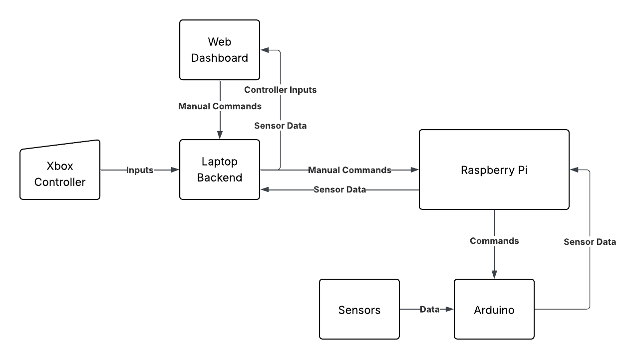
Expressed in more specific language, the architecture is as follows (taken from the repository docs)
Raspberry Pi Layer
The Raspberry Pi layer serves as the central processing unit of the system, handling higher-level logic, data processing, and communication with the web interface. It runs a Python application that processes incoming sensor data, makes decisions based on that data, and sends commands to the Arduino. It hosts a FastAPI web server that uses websockets to listen for manual input from the web dashboard and also send sensor data to be displayed.
The Raspberry Pi is powered by a portable anker power bank. This is the safest option compared to using batteries directly
Key Components
- FastAPI Web Server: Hosts the web interface and handles incoming requests from the web dashboard.
- Serial Thread: A dedicated thread for handling serial communication with the Arduino, ensuring that sensor data is read and commands are sent without blocking the main application.
- Sensor Data Processing: Processes incoming sensor data from the Arduino, including ultrasonic distance, IMU data, and IR sensor flags. Uses asyncio for non-blocking operations such as sending commands and emitting sensor data to the web interface.
- WebSocket Communication: Uses websockets to send real-time sensor data and receive manual control commands from the web interface.
The raspberry pi is formatted with a headless version of Raspberry Pi OS, which is a lightweight version of the operating system without a graphical user interface. This allows for better performance and lower resource usage, as the pi is only used for running the FastAPI server and communicating with the arduino.
Arduino Layer
The Arduino hardware layer is responsible for interfacing with the physical components of the robot, including motors, sensors, and displays. It handles low-level operations such as reading sensor data, controlling motor speeds, and managing communication with the Raspberry Pi via USB serial. Sensor data is collected at specific intervals and sent to the raspberry Pi via a request-response mechanism. The Arduino also listens for commands from the Raspberry Pi to control motors, displays, and other hardware components.
Web interface Layer
The web interface layer provides a user-friendly dashboard for monitoring and controlling the robot. It allows users to view real-time sensor data, control motor speeds, and trigger emergency stops. It has 2 parts, the web dashboard and the web backend.
Web Dashboard
The web dashboard is built using SvelteKit with the following features: Real-time sensor data display, Manual control of motors, Navigation controls (forward, backward, left, right), Battery level indicator, AI natural language control (using OpenAI API), Record and playback of commands/joystick macros
Web Backend
The web backend is built using Flask and serves the web dashboard. It handles requests from the web interface, processes them, and communicates with the Raspberry Pi via websockets. It also uses pygame to handle joystick rumbling and input events for manual control.
Implementing the architecture
With the architecture finally planned out, I could start implementing the different layers, building on what I had already done with the arduino.
First, I had to define a set of commands that the arduino could execute and receive from the raspberry pi. We would have a command for setting the motor speeds, a command for emergency stop, and command for updating the LCD.
The sensor data would instead be sent by the arduino at regular intervals without any need for a command.
With this command structure, I needed to set up the binary packets for each command. Just like with the sensor packet, I would also have a start byte and checksum byte.
Here are the commands (adapted from the serial packets documentation):
- 0x01 - Motor Command
- 0x02 - LCD Command
- 0x04 - Emergency Stop
- 0xAA - Sensor Data Packet
Then the motor command would have the following structure:
The LCD command would be similar but larger since each line in the LCD can have up to 16 characters, and we would send both lines of the LCD.
Finally, the emergency stop command would just consist of the start byte and checksum:
Sending and parsing commands
On the arduino side, the process of reading from the serial port is basically the same as just connecting the arduino to a laptop.
We just need to use the Serial.read() and Serial.available() functions to read the incoming data. Sending data just needs the Serial.write() function (which is the same as Serial.print() but for binary data).
Serial.available() tells us how many bytes are available to read from the serial port. When this is greater than 0 we can create a buffer and read data until we reach the end of a packet.
By checking for the start byte, we can know how long the packet is supposed to be, and then read that many bytes into the buffer.
The expected_command_length function just returns the length of the command based on the first byte (the packet type).
Then, the handleCommand function just checks the command type and processes it accordingly.
Ignore the 0x03 command for now, which I will get into later.
I use strncpy to copy the strings into a buffer rather than directly using
lcd.print. This is to only update the LCD at certain intervals so as to
speed up the command processing and avoid unnecessary updates. The lcd.print
function is quite slow, so we only update the LCD every 500ms and when the
content has actually changed.
Sending data
Now that I had command and sensor data processing, I needed to implement the "write" functionality (i.e. sending commands to the arduino and sending sensor data to the raspberry pi), and actual read functionality on the raspberry pi.
Sending sensor data was very simple, we just send the sensor packet at a certain interval (e.g. every 100 ms), just as how we implemented the caching of sensor data earlier.
I already had the process_data function to unpack sensor data, so before I moved on, I needed to write code to actually read the sensor data from the arduino and process it.
With the SoftwareSerial and bluetooth bottleneck gone, I could use much higher baud rates, so I decided to use a baud rate of 115200 bits/second. This doesn't sound like much (only 11.5 kB/s), but with the 24 byte sensor packet, this means we can send a packet every 2 ms, which is more than enough for real-time sensor data.
I was wondering whether to just use the synchronous pyserial library on the raspberry pi, or use an async version like pyserial-asyncio. The async version looked promising wince we wanted to handle different IO tasks concurrently without blocking. So I decided to use the pyserial-asyncio but unfortunately I just couldn't get it to work.
I tried a bunch of random fixes, but anyway async versions of popular libraries are always a pain to work with, so I just decided to use the synchronous pyserial library. This wasn't so bad because I could just run the serial reading in a separate thread to effectively make it non-blocking.
The code for reading serial data is very similar to the arduino command processing code.
This code is part of a bigger SerialManager class that also handles writing commands.
In the __init__ function I set self.serial = serial.Serial(port, baudrate)
to open the serial port. On a raspberry pi I found that usually the arduino
shows up as /dev/ttyUSB0 but this can sometimes change, so I added a small
script later on to scan the serial ports and find the correct one.
Major serial issue
After implementing serial reading and writing from both sides, I ran into another major issue. Whenever I sent any command to the arduino, there was a chance it would just stop responding and not send any sensor data. I tried debugging this for a long time, but I just couldn't figure out what was going wrong.
That was until I learned about full and half-duplex communication. When I sent the command to the arduino, there was a chance that the arduino was already sending sensor data at the same time. This would cause a collision on the serial line, and the arduino would just stop responding. This was a major issue because I had no way of knowing when the arduino was sending sensor data, and when it was ready to receive a command. So I had to pivot from sending sensor data at intervals to using a request-response mechanism.
Request-Response Mechanism
The request-response mechanism is a common pattern in client-server architectures where the client sends a request to the server and waits for a response. In our case, the arduino is the server and the raspberry pi is the client. This allows us to know exactly when we are waiting for a response, and using this we can avoid collisions on the serial line.
So, instead of sending sensor data at intervals from the arduino, I changed the code to send a sensor request command at intervals from the raspberry pi (This is the 0x03 command I mentioned earlier).
But what if we also had to send a command to the arduino? This could also be easily handled just by keeping a flag to indicate that we are waiting for a response. If the flag is true, we don't send any commands to the arduino. The flag is then reset when we receive a response. This also goes for sending the sensor request command. If we are waiting for a response, we don't send the sensor request command. Finally, whenever we do send a command, we set the flag to true.
An important addition I made to the arduino code was to send sensor data no matter what command was received. Even if the command isn't a sensor query command (0x03), we still send back sensor data so that we can get continuous sensor updates. Picture this, if we only sent sensor data when a sensor command is received, we would get no updates while motor commands are being sent, effectively making the robot "blind" while moving. Another useful thing about this method is that each sensor response serves as an acknowledgment for the command sent, so we can be sure that the command was received and processed correctly.
If we go back to the arduino loop function, we can see this in action:
Now instead of setting bufferSensorSetting to true at a certain interval, we set it to true when we received a command.
I put this at the very end of the loop because I noticed sending sensor data right after setting the motors would result in nothing being sent. I think this is because the motors take some time to start moving, and the arduino is busy processing the motor command, so it doesn't have time to send the sensor data. So I just put it at the end of the loop to ensure that all commands are fully processed before sending sensor data.
The Robot Class
We already have serial communication figured out between the arduino and raspberry pi, but now we need to actually request sensor data, process it, and send commands to the arduino.
For this, I created a Robot class that handles communication above the serial layer, and also processes sensor data and sends them to the laptop.
I ended up having the robot class taking the SerialManager class as a parameter, ann the SerialManager class taking the Robot class as a parameter. This is because the Robot class needs to send commands to the arduino, and the SerialManager class needs to read sensor data from the arduino and call the process_sensor_data method of the Robot class.
I also made the Robot class methods fully asynchronous, so that I could use the asyncio library to handle concurrent tasks (e.g. querying sensor data, sending commands from the laptop, sending data). Along with this, I also used the asyncio.Event class to handle the request-response mechanism.
asyncio.Event() is a simple synchronization primitive that blocks a coroutine (process) until the event is set. In this case, we use it to block sending any sort of commands to the arduino while we are waiting for a response. Two other important uses are for the cliff and obstacle detection. Specifically, if a cliff or obstacle is detected we unset the Event to temporarily block commands until the robot has cleared the obstacle or cliff. This is important to prevent the robot from running into a cliff or obstacle again and again while it is backing up. Also, this prevents spamming of obstacle or cliff detection (e.g. the robot is 5cm away from the wall, we trigger the obstacle detection. Without these events the robot will detect the obstacle again the next instant and again and again) .
Another important primitive is the asyncio.Lock() method. This creates a mutex that I use to ensure only 1 command is sent at a time. Specifically, using asyncio.Lock ensures that only 1 process has access to the current resource at this instant. This is important since we have different processes that can send commands: the sensor request loop, the manual control from the laptop, and AI commands (which I will get into later).
Finally, we also take in a socketio parameter to allow the robot class to emit sensor data to the laptop via socketio. This is used to send real-time sensor data to the web interface, receive manual control commands, or even send "rumble" commands to the laptop to initiate haptic feedback when obstacles or cliffs are detected.
We set up the Robot class as follows:
This sets up the basic structure of the Robot class, and initializes the important variables and events.
Then we can initiate the sensor request loop, which is a coroutine that runs in the background and requests sensor data at regular intervals. This is done using the asyncio.create_task() method to run the sensor_request_loop coroutine in the background.
The FastAPI server
To actually connect to the raspberry pi from my laptop I would have to set up a webserver, and I chose to use FastAPI because of its simplicity and async nature. I also chose to use socketio instead of a traditional REST API because I wanted to have real-time communication between the laptop and the raspberry pi. This would allow me to send commands and receive sensor data in real-time without having to poll the server for updates.
The server would listen for the following events from the laptop: joystick_input, query (AI command query), and stop (emergency stop command). It would also emit the following events to the laptop: sensor_data, rumble, and active_command (for the AI control).
The server code is again pretty simple, we just set up a FastAPI app and use the socketio library to handle the events.
We run the server on host 0.0.0.0 to make sure that it is accessible from any other device on the network.
Finally, the event listeners just call the corresponding methods in the Robot class to handle the joystick input, AI query, or emergency stop command.
The Robot Class Methods
As you can probably already tell, the Robot class is the main controller for the robot. It basically integrates all data sources and handles the logic for controlling the robot.
As discussed earlier about the synchronization primitives, we can now implement the methods for sending commands safely, and controlling the robot from joystick data or AI queries.
First, the send_safe_command method uses the asyncio.Lock() motor_lock mutex and the waiting_for_sensor event to ensure that we only send one command at a time, and that we are not waiting for sensor data before sending a command.
Using this method above we can implement joystick input:
Notice that we check if the cliff_clear, waiting_for_sensor, and
obstacle_clear events are set before sending the command. This ensures that
we only send commands when the robot is not in a cliff or obstacle state, and
that we are ready to receive sensor data.
The Command Class
You may have noticed that we also have this Command class that seems to have methods for creating commands from joystick input or other sources. This class is also simple data structure (using pydantic) that holds the command type, ID, and any additional data needed for the command.
The other pydantic models represent different types of commands, such as LCDCommand and MotorCommand.
This leads to one more question: how do we actually convert joystick input to 2 motor speeds?
Arcade Drive
There are actually quite a few different ways to do this, and there are many different ways to control a differential drive robot from a joystick. But later on we will see that we can convert different joystick mappings to 2 values: y and x.
Now we need to convert this y and x to 2 motor speeds. The simplest way to do this is to use the following formula:
This is known as arcade drive, and the way it works is really simple. The y value controls the forward and backward movement of the robot which is why we add it to both motors. The `x value controls turn, and it's important to note that on a joystick, the x and y values can range form -1 to 1. For the x-axis, left is -1, and right is +1. This is why we add x to the left motor and subtract it from the right motor. This way, when we turn left, the left motor will slow down and the right motor will speed up, causing the robot to turn left. When we turn right, the opposite happens, and the robot turns right.
There's still a bit more to do after this. First, the l and r values need to be scaled to -255, and 255, and before that they need to be clamped between -1 and 1 to be properly scaled.
This works pretty well for driving the robot, but soon you'll notice that even moving the joystick slightly will cause the robot to move (or not move). If the calculated motor value is too low but not 0 (usually less than 50), the voltage delivered by PWM is too low to overcome the static friction of the motors, so the robot doesn't move. To overcome this we first need to set a deadzone for the joystick. This means that if the joystick is moved less than a certain threshold, we stop the robot and don't do anything else.
Finally, we have to clamp the final motor values so their magnitude is greater than our minimum (usually 50 or 60).
The Command class implements these methods:
Making it "smart"
Going back the SerialManager class, remember this line of code that runs when we receive a sensor packet from the arduino:
The self.loop_call_soon_threadsafe is just a way we can call something async from the synchronous serial manager context. But the real important part is calling robot.process_sensor_data(p). We already have manual control of the robot taken care of with the FastAPI server and joystick calculations, but this process_sensor_data method is where we make the robot actually smart. This method will actually use this data to avoid obstacles, "rumble" or use haptic feedback on the xbox controller for alerts, and detect cliffs.
Let's break this down step by step:
- Waiting for Sensor Data: We set the
waiting_for_sensorevent to indicate that we are no longer waiting for sensor data (I should have changed the terminology but basically this just says "we have received sensor data and can safely send commands now").- Going back to the
send_safe_commandmethod we wait for this event to be set before sending any commands:
- Going back to the
- Processing Sensor Data: We convert the bytes received from the arduino into a
SensorDataobject using thebytes_to_sensor_datamethod that I talked about earlier. This method unpacks the bytes into the corresponding sensor data fields. - Handling Obstacles: We call the
handle_obstaclemethod to check if there is an obstacle in front of the robot. This method uses the ultrasonic sensor data to determine if there is an obstacle within a certain distance threshold (20 cm in this case). If an obstacle is detected, we emit a rumble event to the laptop and set theobstacle_clearevent to false, which will block any commands from being sent until the robot has cleared the obstacle. Finally, we return the distance measurement (adjusted if invalid as explained previously) so that we can store it in our distance history and apply a low-pass filter.
Notice that we check if the rumble_cooldown has elapsed before sending a rumble command to prevent spamming. Again, we return the processed distance measurement as avg_distance and check if this is less than 20 cm to trigger the obstacle avoidance. Finally, we create a task to back up the robot and reset the obstacle_clear event after a certain cooldown (to prevent commands from coming in as we are backing up). This backup function just sends a motor command, then waits for a bit, and finally sends a stop command.
- Handling Cliffs: We call the
handle_cliffmethod to check if the robot is about to fall off a cliff. This method uses the IR sensors to determine if the robot is about to fall off a cliff. If a cliff is detected, we emit a rumble event to the laptop and set thecliff_clearevent to false, which will block any commands from being sent until the robot has cleared the cliff.
- Emitting Sensor Data: Finally, we emit the sensor data to the laptop using the
socketio.emitmethod. This allows us to send real-time sensor data to the web interface for display and analysis.
Putting it all together
The Robot class is now setup along with the SerialManager class, the FastAPI server, and our pydantic models including the Command and SensorData classes. Now we need to run all of these together in a main function.
First, we find the serial port using the find_port method in the SerialManager class. This method scans the serial ports and returns the first one that matches the arduino's USB device name. If no port is found, we log an error and exit.
Then we create an instance of the SerialManager class with the found port and a baud rate of 115200. We also create an instance of the Robot class with the SerialManager instance and the socketio instance.
Next, we get the current event loop using asyncio.get_running_loop() and start the serial manager in a background thread using the start method. This method starts the serial reading loop in a separate thread so that it doesn't block the main thread.
Finally, we run the FastAPI server using the run_socket_server function, passing in the robot instance to handle the events.
This is the main entry point of the application, and it sets up everything we need to run on the robot side.
The Laptop "UI Hub"
The raspberry pi is now fully capable of communicating with the arduino and processing sensor data, but we still need a way to control the robot from the laptop. For this, I set up a simple flask web server on my laptop that integrates with pygame to handle xbox controller input.
The web server also connects as a client to the raspberry pi's FastAPI server using socketio. This allows us to send commands to the robot and receive sensor data in real-time. Then, the web server also emits the sensor data to the SvelteKit web interface which sends back manual commands (these commands from the UI are forwarded to the raspberry pi via socketio).
For the web server, I define the following events just as in the FastAPI server on the raspberry pi:
Frontend Events
joystick_input: This event is emitted by the web interface when the user uses their keyboard arrows or presses buttons on the web dashboard. It is also emitted by the laptop server to the frontend when the user uses the xbox controller. The server then sends this joystick input to the raspberry pi to control the robot.query: This event is emitted by the web interface when the user asks a question or gives a command to the AI. The server then sends this query to the raspberry pi to process it and send back a response.stop: This event is emitted by the web interface when the user wants to stop the robot immediately. It is also triggered and sent to the web frontend when the user presses theBbutton on the xbox controller. The server then sends a stop command to the raspberry pi.joystick_mode: This event is emitted by the web interface when the user selects different joystick control modes:2 Joystick Arcade Drive,1 Joystick Arcade,Tank Drive, and a customCar mode. This event can also be emitted by the laptop if the user sues the xbox bumper buttons to switch between joystick modes. On the laptop this changes the calculation of x and y values.precision_mode: Precision mode reduces the speed of the robot to 50% when enabled. This is useful for precise movements and avoiding collisions. This can be toggled in the web interface or by pressing theybutton on the xbox controller.start_recording: Recording is a special feature that allows for replayable macros of joystick movements. You can start recording, move the robot in a desired path, and then stop recording. The recorded movements can then be replayed later. Recordings can be started from the web interface or by pressingXon the xbox controller.stop_recording: This event is emitted by the web interface when the user wants to stop recording the joystick movements. It is also triggered when the user pressesXon the xbox controller while recording.play_recording: This event is emitted by the web interface when the user wants to play the recorded joystick movements. It is also triggered when the user pressesAon the xbox controller while recording.- Note: I did not add a
pause_recordingorstop_playingevent yet since it wasn't fully necessary for demoing, but I will add it later on.
Raspberry Pi Events
sensor_data: This event is emitted by the raspberry pi when it receives sensor data from the arduino. The laptop server then emits this data to the web interface for display.rumble: This event is emitted by the raspberry pi when an obstacle or cliff is detected. The laptop server rumbles the xbox controller via pygame as specified in the data.active_command: This event is emitted by the raspberry pi when an AI command is being processed. The laptop server then emits this event to the web interface to display the active command.
These events are all setup in the main file of the laptop server:
The Controller Class
Under the hood, pygame uses SDL (Simple DirectMedia Layer) to handle input from the xbox controller. The Controller class uses the pygame.joystick module to read input from the xbox controller and trigger haptic feedback.
In this, we have to implement joystick macros (recordings), different joystick modes, and also rumble functionality.
The gesture controller is from my other project where I took an old, undocumented RISC-V based board and used the onboard electronics to turn it into a gesture controller. It uses an accelerometer to detect gestures and sends them to the laptop via a simple HTTP API. The Controller class can use this gesture controller to control the robot in addition to the xbox controller.
Before we can do anything with the xbox controller, we have to initialize it. This is done in the initialize method:
In the first code snipptet, I define cooldown flags along with our feature flags. These are used to prevent rapid state switching because pygame's API returns 1 while a button is being pressed down. If we only check that the button is 1, then we will keep switching while the button is being held. Instead, we can either give the button a cooldown (i.e. the button won't trigger any state switching for the cooldown duration after being pressed) or we can check if the last button state was 0 (not pressed) and the current state is 1 (pressed). This way we only switch states when the button is pressed down, and not when it is held down. While figuring this out I ended up implementing the cooldown based approach.
So, we define a method called is_button_ready to check if a button is pressed and the cooldown has elapsed:
Now that we can get input from the xbox controller buttons, we need to define some different modes for our controller. I did this with a ControllerState enum:
I defined 5 different modes, each with its own way of controlling the robot. The ONE_ARCADE mode uses the left joystick's x and y values as inputs for arcade drive while the TWO_ARCADE mode uses the x value from the right joystick and the y value from the left joystick. Next, the TANK mode uses the left joystick to control the left motor and the right joystick to control the right motor. The CAR mode is a bit different, it uses the right trigger as an accelerator and the left trigger as a brake, while both joysticks are used for steering. When the accelerator is pressed, the robot gains speed and maintains this speed until a few seconds after the accelerator is released (kind of like a car). Finally, the GESTURE mode uses the accelerometer data from the gesture controller to control the robot.
To actually switch between states I added a manage_state function that just checks if the right or left bumpers are pressed to "scroll" through the states and update self.state accordingly. This function also takes a state parameter which is used when the user changes the state with the frontend.
And to implement probably the coolest feature, haptic feedback, I used pygame's rumble method on the controller instance:
Finally, I needed 2 more functions before I could work on the main loop (send_update): one to actually read joystick input, and one to determine whether to send joystick input or not (to avoid spamming when the joystick is in the middle).
The function to read joystick input just reads both joysticks and adjusts them based on the current state:
Then we only send input when the joystick has moved enough to be outside the deadzone.
The frontend can also send joystick input through the joystick_input event, so we need to handle that as well. The handle_joystick_input method is called when the frontend sends joystick input, and it just directly sends the joystick data to the raspberry pi via socketio:
I send joystick update events to the frontend so that the UI can update the joystick position and display the current state of the robot. This is useful for debugging and monitoring the robot's state.
I won't go into too much detail for the recording features, but they just record the joystick input and save it to the self.joystick_history list with a timestamp. This is done by the start_recording and stop_recording methods which are mapped to the X button but also available in the frontend. Both methods send events to the frontend to update the dashboard. Finally the play_recording method just sends the joystick data to the raspberry pi at 10hz. When started from the frontend, it takes a timestamp to select a specific recording. When started via the A button, it just plays the latest recording.
Finally, precision mode is toggled by the Y button or the frontend, and it just sets a flag that reduces the speed of the robot to 50% when enabled. This is useful for precise movements and avoiding collisions.
Now, we can implement the send_update method which is called in the main loop to send joystick input to the raspberry pi:
Just like the Robot class, this method reads input from the frontend, xbox controller, and gesture controller, and sends joystick data to the raspberry pi and the frontend. It also handles the different states and features like precision mode, recording, and playback.
Frontend Dashboard
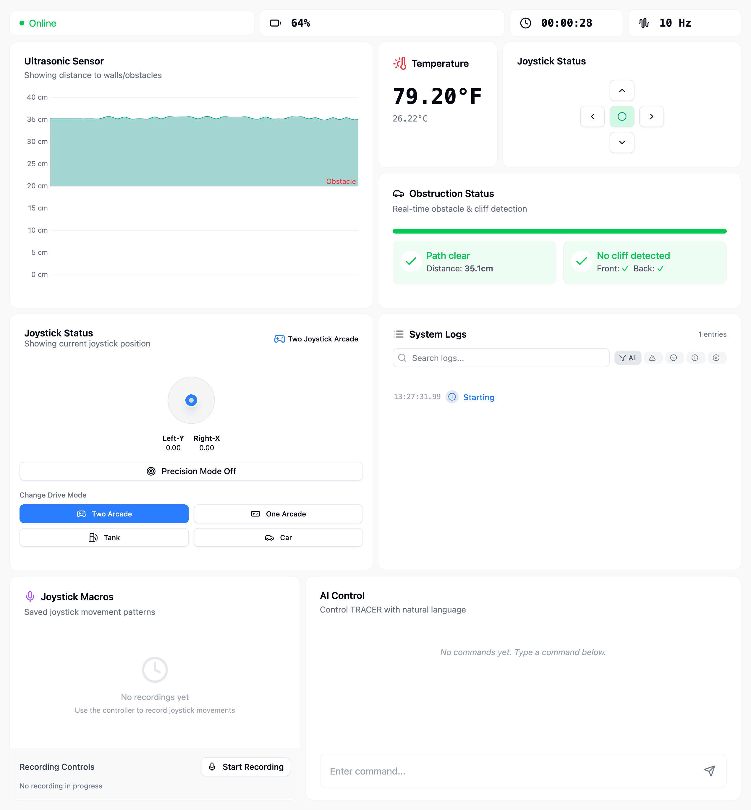
I tried to make the dashboard look as modern and sleek as possible, while still being functional. The dashboard is built with SvelteKit and uses Tailwind CSS for styling. Just like the laptop and the raspberry pi, the frontend connects to the laptop backend via socketio to receive sensor data and send commands.
Along with being able to control the robot with keyboard arrows, I also added a graph for the ultrasonic distance data, and a section for obstacle and cliff status. There's also an area to change controller states and start / play recordings.
But by far the coolest part is the AI control.
AI Control
This is the ultimate goal of the project: to be able to control the robot with natural language commands. All of the work before has built up to being able to do this.
First, we must break down this problem into a series of steps. We already have a set of commands that we can send to the arduino (motor, lcd, and stop commands). We also have a way to get user input from the web dashboard. Now the goal is, how do we convert a user query into a set of commands that the robot can execute.
I thought about how to do this for a while, and I realized that using LLMs with structured outputs was probably the easiest way to do this. Most LLMs nowadays can return structured JSON data which adheres to a specified schema. I just have to make an AICommand pydantic model that defines the schema of the JSON response. Then we can use this to get the set of commands to execute.
However, it's not so simple. What if the user asks "move forward then pause for a bit and then move backward"? We also need a way to specify how long or how far a command should run. Specifying distances is only feasible with motor encoders, so I opted for duration. If we go back to the Command class, I added 2 extra fields: duration and pause_duration. The duration field specifies how long the command should run, and the pause_duration field specifies how long to pause before executing the next command.
This class just specifies a command, but there are multiple types of commands that we can send (LCD, motor, stop), so we need to specify the actual command type in the command_type field. Then we can use the command field to store the actual command data. The pause_duration and duration fields are only used for AI commands, so they are not required for manual commands.
The LCD Command just stores both lines of text to display:
And the motor command just stores the left and right motor speeds:
The stop command doesnt need any data, so it doesn't need a model. We can identify it just by checking the command type in the Command class.
I add descriptions to the fields so that the LLM can understand what each field means. This is useful for generating the JSON schema and for the LLM to understand what data it needs to return.
Finally, we need to allow the LLM to return an array of commands, not just one. So, I created an AICommand class that just contains an array of Command objects:
Now that we have the command schema, we just need to prompt the LLM so it performs better at the task. In the system prompt, I specified the role of the LLM as a "robot command interpreter" and then explained the available commands and how they should be used:
Finally, we need to implement the text_to_command function that takes a user query and returns a list of commands. For this, I decided to use the OpenAI API with the gpt-4.1-nano model, which was the cheapest.
I set the max output tokens to 500, which is more than enough for the commands
we need to generate. The temperature and top_p parameters control the
randomness of the output, and I set them to 1 to allow for more creative
responses.
With the command generation complete, I just needed to get user input from the frontend and send it to the text_to_command function.
When a query is submitted, we send a socketio event to the laptop backend, which then sends it to the raspberry pi via socketio. The raspberry pi then calls the handle_query method of the Robot class, which uses this text_to_command function to convert the query into a list of commands.
As a nice touch, I made it so that while we are generating the commands, the robot displays "Thinking..." on the LCD screen.
But now we actually have to execute the commands, which is where the _run_command_sequence method comes in.
Notice that I run the command sequence in a task. This prevents it from blocking any other process that sends motor commands, and this allows the obstacle avoidance and manual control to be active even while the AI commands are executing.
In this function, I just iterate over the commands and then send each one and pause for the command's duration. I also emit an "active_command" event which just sends the command to the laptop and frontend. If the command does have a pause duration, we also pause for that amount. Once all commands have been sent, we stop the robot and send an empty "active_command" event to clear the active command on the frontend.
Sending the "active_command" event is really useful since it allows the frontend to display the current command being executed. This creates the reelly cool effect of commands loading in as the robot is "thinking."
Demos and images
Conclusion
This project took about 3 weeks to complete excluding the planning time before. It was a lot of fun and also challenging to implement, and i learned a lot about robotics, binary, communication protocols, hardware, and AI. This project also led me on another project right after where I took an old, unused, undocumented RISC-V board and turned it into a gesture controller using the onboard accelerometer. This project, in my opinion, was even harder and more challenging, but just as rewarding. You can check it out here: Gesture Controller.